

Sometimes, things get in the way in our lives. And sometimes, it’s best to take advantage of otherwise displeasing situations. With creativity and a firm conviction that we can succeed, anything is always possible.
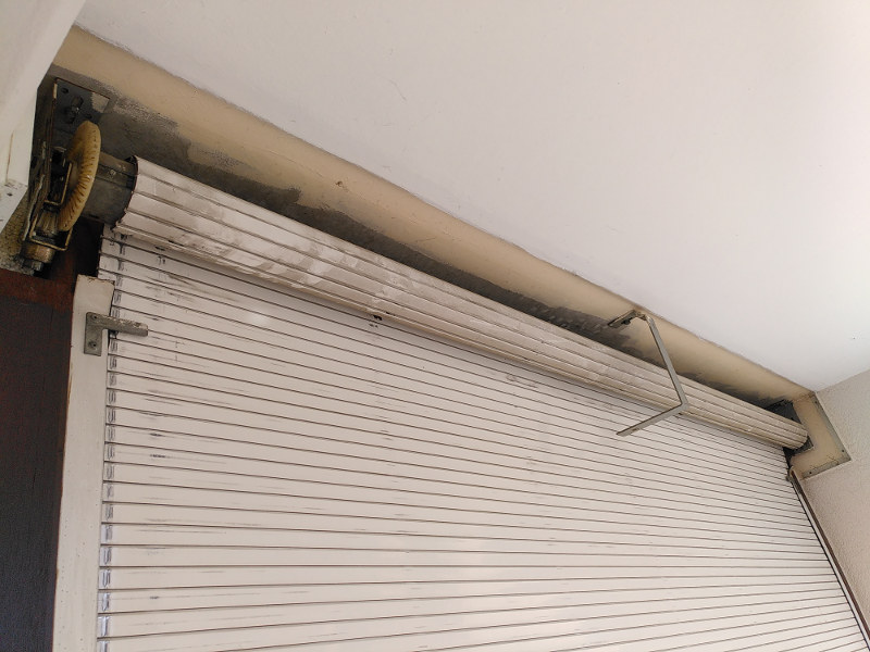
Our apartment building is almost 50 years old. After that much time, some things start falling apart. Like roller blinds.
Assessing the problem
The first time those things failed, almost 10 years ago, it was an easy fix. One central part of the mechanism is a plastic piece with a square hole, that receives the crank handle. That plastic piece got loose over the years until it burst open.
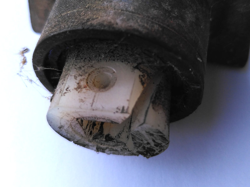
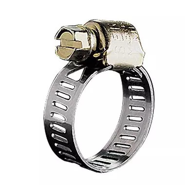
A simple sleeve clamp did the job of making the plastic hold the connector tightly, and had the whole thing running for another 10 years.
However, what came next was at a different level. The central piece of the mechanism, a piece with a ball bearing in it that rotates only when maneuvered by the crank handle, became stuck. For good. Of course, there are currently no replacements for this kind of piece.
So I had a shutter in perfect condition, except for that piece. I knew that calling a repairman for this would have me replace the whole shutter, “because it’s not compatible” (and additionally to maximize profit, spending time doing custom jobs is not efficient when it comes to money, which is sad because that’s exactly what we would need at a civilization level right now), etc. What a waste it would be!
Devising a solution with 3D printing
I figured that I could actually take advantage of the situation, and I could even put an electric engine in my roller. Many people laughed when I said I was planning to go electric on a failing manual mechanism.
I launched OpenScad and designed some pieces. I ordered an engine that I knew would handle the weight (100 kg, 50 Nm, less than 50 euros).
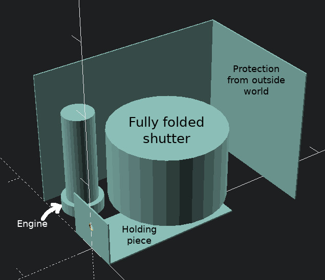
It so happens that today’s standards are very different from that time’s. At the time, they had large cylinders with a diameter of almost 10 cm. Nowadays, we have octagonal rollers that are about 6 cm large. So, today’s engines surely don’t fit into a 10 cm cylinder – well you can insert it in it, but having it secured inside is a challenge. This is especially true as all the force needed to raise the shutter is transferred there. Besides, the roller itself is impossible to disassemble. And it’s quite large and massive, difficult for one person to handle alone.
Physical Constraints
Besides, I had to take into account the weight of the whole shutter: it’s an old thing, and probably weighs around 50 kg, maybe a bit more. Besides, the roller itself probably weighs 20-30 kg on its own. Needless to say, my solution had better be strong. Fortunately, I’ve already had experience with plastic.
Plastic is generally viewed as fragile. After all, when a mechanical part fails, it is a piece of plastic 95% of the time. However, plastic, even PLA which is my preference because of its low environmental footprint, can be quite sturdy. People have even printed propellers with it:
My experience is that combining a plastic structure with metallic backbones is quite indestructible. Very small pieces can hold a lot of weight if designed properly. For instance, these shelf supports can hold a lot of weight. And I mean, a lot:

Note how the weight is actually mostly on the horizontal steel screw, the plastic is just a proxy in between, as well as having some extra support from those two other screws on the shelf – which is also a cubic structure so there is no angular pressure on the support.
First Failure – Design
As I didn’t want to damage the roller, I first thought of having the engine outside the roller and connecting it with gears but there were a couple of problems:
- there is very very little space for the engine when the shutter is totally rolled up,
- tightening the engine securely for the kind of forces at play would be challenging,
- I had doubts about the solidity of 3D printed gears, especially on the long run,
- the engine has two parts: one for traction, one for counting the number of turns in order to stop when the shutter is fully open or closed. Making that second part turn in sync with the first was not an easy thing to do in a reliable way with what I had in my toolbox.
After trying out several designs, I had to give up that path. Not that it was impossible, it would be feasible to squeeze that engine outside and fix some gears. But it involved many pieces and the risk of something failing sooner or later. I didn’t want to take the chance.
Second solution – and failure
So I had to cut the roller open to insert my engine inside. Reluctantly, I cut the end part of the roller:

I know, it doesn’t look pretty. I probably could have used an angle grinder. I burnt a couple of blades in the process:

Unfortunately, I had bad news: inside was a wall, very likely welded in, that I would certainly not be able to remove. I was stuck.

Getting back up
At that point, I figured I could as well cut the other end and see if I would be luckier… and I was! That side was definitely empty so I could resume the project. The next step was to measure and design the necessary 3D pieces:
- some holding piece on one end with a ball bearing for the whole thing to turn smoothly, and again, note how the plastic is just a proxy between metallic parts ; you can see the ball bearing encased in the plastic:

- on the engine’s side, fillers that would match the engine’s octagonal and somewhat weird shapes on the inside, and the cylinder on the outside,

- drilling holes in the shaft to host the holding screws:
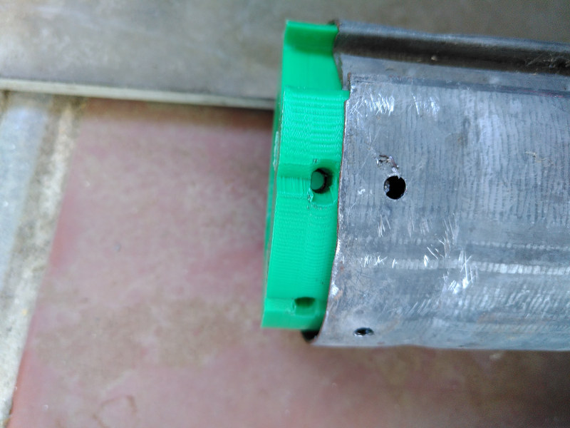
- Fitting the pieces together:
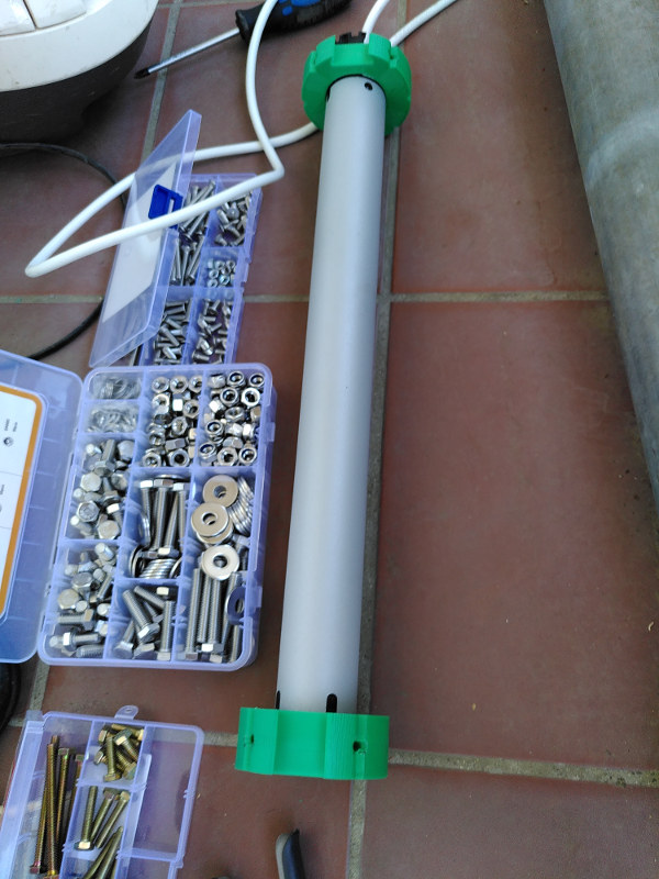
Putting the external support in place:

This last piece has several functions.
- first, to hold the whole structure vertically: engine+roller. This is achieved thanks to the 4 horizontal screws, which actually are the ones taking all the weight.
- second, to enable rotating the whole structure while blocking on the hexagonal corners, this can be useful if the whole thing becomes stuck, for instance, otherwise you would be in trouble with a non-rotating shutter and no way of unscrewing it due to the lack of space,
- third, to have those 3 screws distribute the load of the rotational forces to the 4 horizontal screws. Again, the plastic is just a proxy here, it doesn’t actually hold anything by itself.
Final setup
Finally, everything looks good:


The last step is the electric setup with a switch (notice the little 3D-printed box under it to hide the electric wiring):
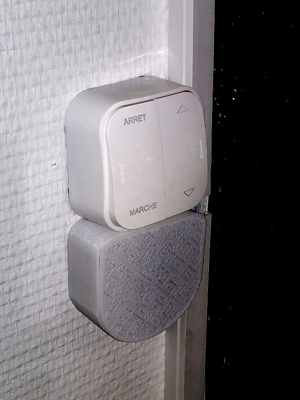
Upon testing, everything works as expected. Hurray!
Just a final note to those of you who do have shutters like this: you *have* to lubricate the sliding parts regularly (at least twice a year) with silicone lubricant. It is the best way of giving a long life to your shutters. Any other solution I tried ended up either in disaster or with very unsatisfactory results.