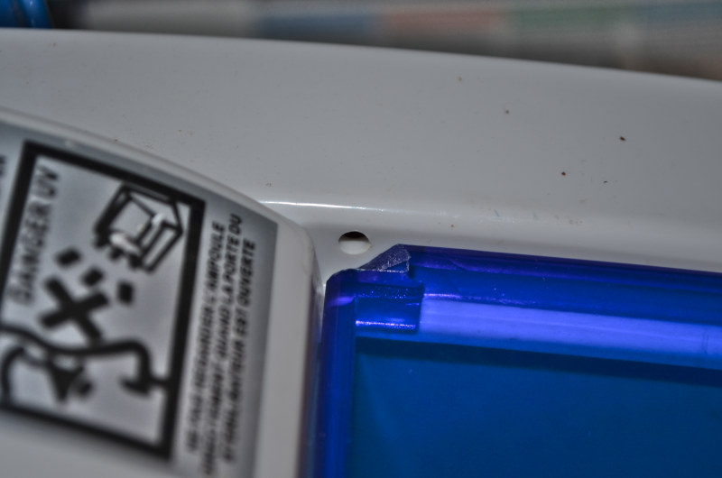
The failing device was a UV sterilizer. Its cover is held by two little plastic notches, which broke. Plastic.
Analyzing the problem
The problem is that, without that little piece of plastic, the whole thing doesn’t work. That’s because there is a little switch that is activated when the lid is closed, and that switch doesn’t get activated.
The tricky part here is that the missing plastic part is very small. It is basically 2mm thick and a few millimeters large. Besides, the hole is higher than the plastic pieces that are left. There is no way we can just put a screw directly inside the remaining plastic.
Additionally, 3D printed pieces have only a limited level of detail. And the less plastic there is, the less robust it is.
The main issue here is that we have to have something go inside this hole to hold the whole cover. There is no way a piece of plastic will handle that. It has to be a screw or bolt.
I also didn’t want to use any glue, so the holding piece should be held by another screw.
Designing the piece
I came up with a very simple design: a screw to hold the printed piece in place, and another screw that acts as a sort of hinge.
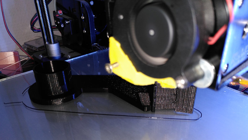
And the printed piece comes to life, notice how we are really reaching the edge of how much detail we can get:
Putting the piece in place
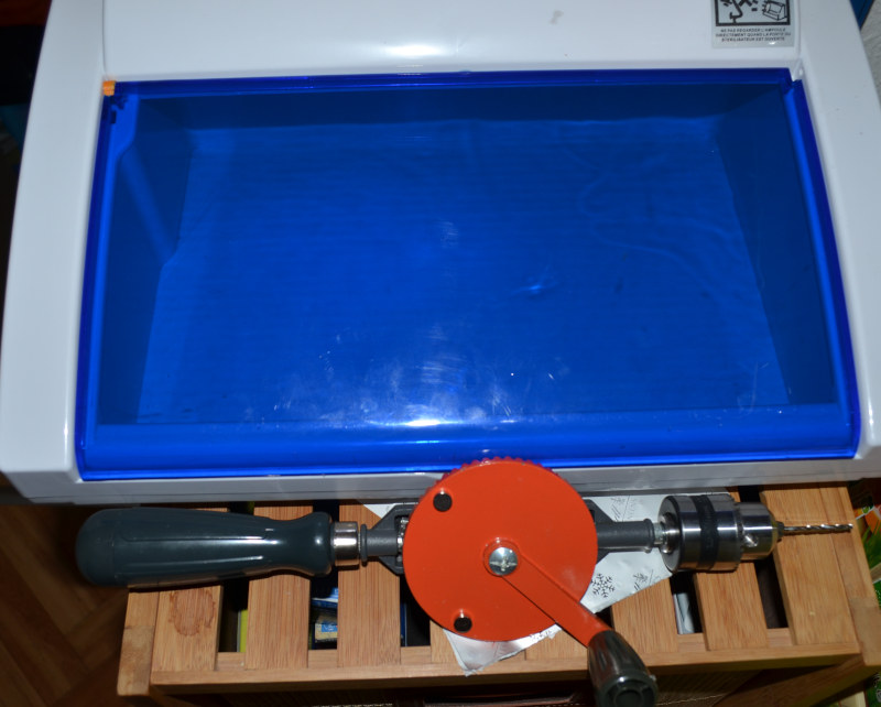
I first needed to drill the existing door’s plastic to fit the holding screw. Low tech drill here:
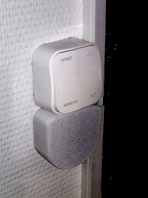
Time for truth: screwing the piece in place and testing it on the machine. In here, you can see the little switch that needs to be activated in order for the machine to work.
Final result
And the final result: a fully functional door again, and a working sterilizer.
3D printer, 4th object fixed without needing to trash things and replace them with new ones. Yay!
Sometimes, things get in the way in our lives. And sometimes, it’s best to take advantage of otherwise displeasing situations. With creativity and a firm conviction that we can succeed, anything is always possible.
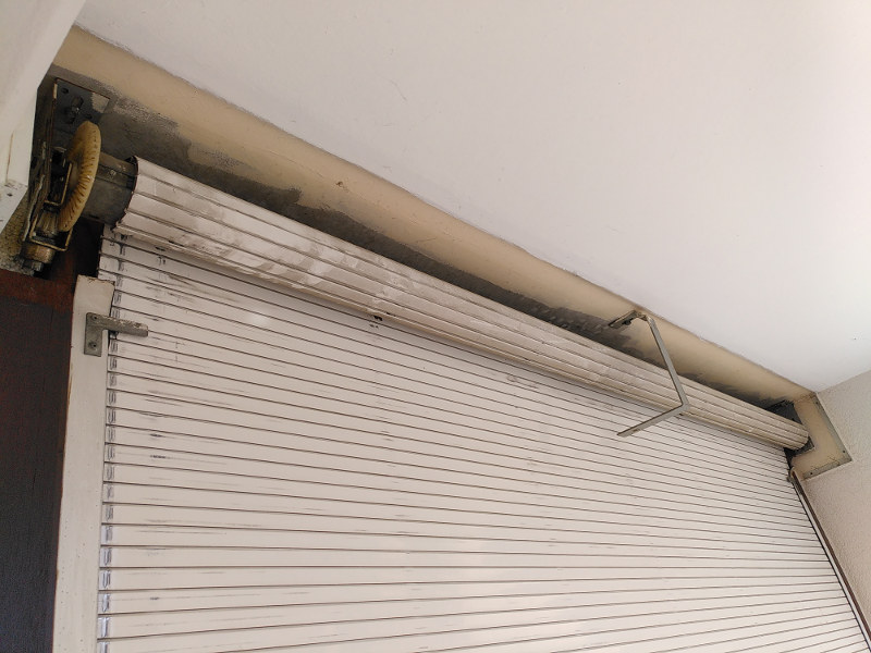
Our apartment building is almost 50 years old. After that much time, some things start falling apart. Like roller blinds.
Assessing the problem
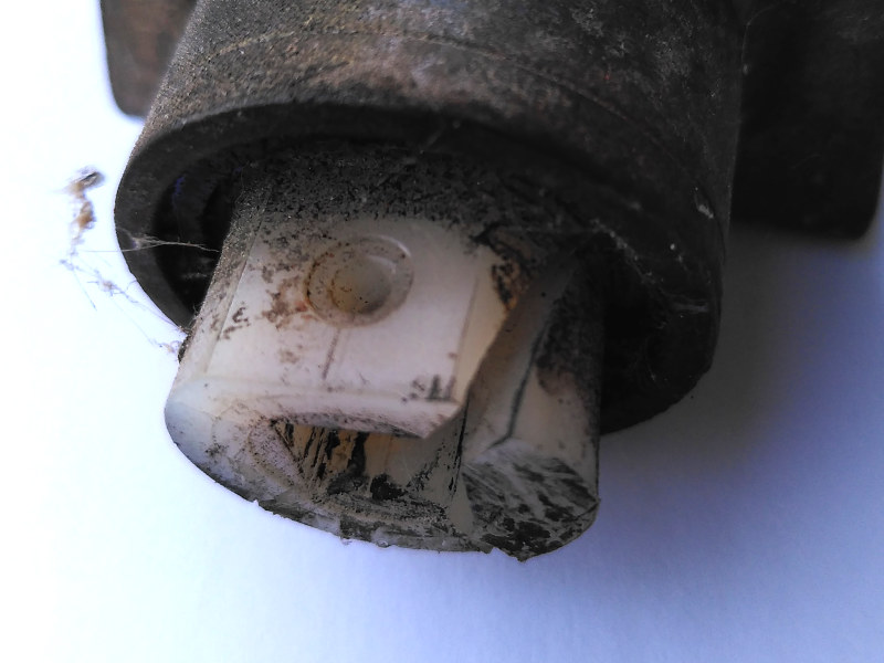
The first time those things failed, almost 10 years ago, it was an easy fix. One central part of the mechanism is a plastic piece with a square hole, that receives the crank handle. That plastic piece got loose over the years until it burst open.
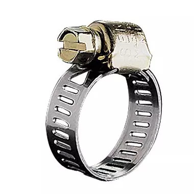
A simple sleeve clamp did the job of making the plastic hold the connector tightly, and had the whole thing running for another 10 years.
However, what came next was at a different level. The central piece of the mechanism, a piece with a ball bearing in it that rotates only when maneuvered by the crank handle, became stuck. For good. Of course, there are currently no replacements for this kind of piece.
So I had a shutter in perfect condition, except for that piece. I knew that calling a repairman for this would have me replace the whole shutter, “because it’s not compatible” (and additionally to maximize profit, spending time doing custom jobs is not efficient when it comes to money, which is sad because that’s exactly what we would need at a civilization level right now), etc. What a waste it would be!
Devising a solution with 3D printing
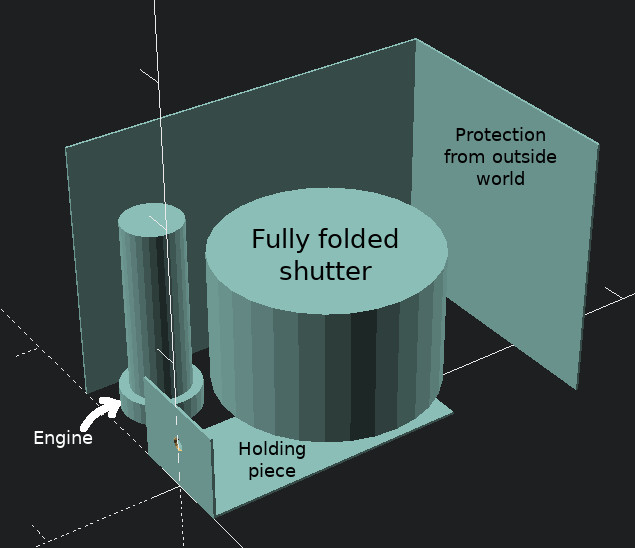
I figured that I could actually take advantage of the situation, and I could even put an electric engine in my roller. Many people laughed when I said I was planning to go electric on a failing manual mechanism.
I launched OpenScad and designed some pieces. I ordered an engine that I knew would handle the weight (100 kg, 50 Nm, less than 50 euros).
It so happens that today’s standards are very different from that time’s. At the time, they had large cylinders with a diameter of almost 10 cm. Nowadays, we have octagonal rollers that are about 6 cm large. So, today’s engines surely don’t fit into a 10 cm cylinder – well you can insert it in it, but having it secured inside is a challenge. This is especially true as all the force needed to raise the shutter is transferred there. Besides, the roller itself is impossible to disassemble. And it’s quite large and massive, difficult for one person to handle alone.
Physical Constraints
Besides, I had to take into account the weight of the whole shutter: it’s an old thing, and probably weighs around 50 kg, maybe a bit more. Besides, the roller itself probably weighs 20-30 kg on its own. Needless to say, my solution had better be strong. Fortunately, I’ve already had experience with plastic.
Plastic is generally viewed as fragile. After all, when a mechanical part fails, it is a piece of plastic 95% of the time. However, plastic, even PLA which is my preference because of its low environmental footprint, can be quite sturdy. People have even printed propellers with it:
My experience is that combining a plastic structure with metallic backbones is quite indestructible. Very small pieces can hold a lot of weight if designed properly. For instance, these shelf supports can hold a lot of weight. And I mean, a lot:
Note how the weight is actually mostly on the horizontal steel screw, the plastic is just a proxy in between, as well as having some extra support from those two other screws on the shelf – which is also a cubic structure so there is no angular pressure on the support.
First Failure – Design
As I didn’t want to damage the roller, I first thought of having the engine outside the roller and connecting it with gears but there were a couple of problems:
there is very very little space for the engine when the shutter is totally rolled up,
tightening the engine securely for the kind of forces at play would be challenging,
I had doubts about the solidity of 3D printed gears, especially on the long run,
the engine has two parts: one for traction, one for counting the number of turns in order to stop when the shutter is fully open or closed. Making that second part turn in sync with the first was not an easy thing to do in a reliable way with what I had in my toolbox.
After trying out several designs, I had to give up that path. Not that it was impossible, it would be feasible to squeeze that engine outside and fix some gears. But it involved many pieces and the risk of something failing sooner or later. I didn’t want to take the chance.
Second solution – and failure
So I had to cut the roller open to insert my engine inside. Reluctantly, I cut the end part of the roller:
I know, it doesn’t look pretty. I probably could have used an angle grinder. I burnt a couple of blades in the process:
Unfortunately, I had bad news: inside was a wall, very likely welded in, that I would certainly not be able to remove. I was stuck.
Getting back up
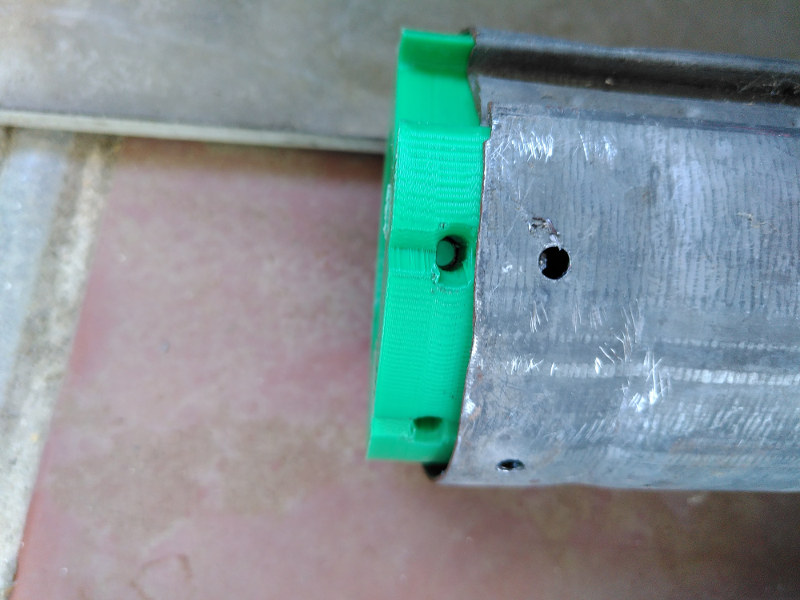
At that point, I figured I could as well cut the other end and see if I would be luckier… and I was! That side was definitely empty so I could resume the project. The next step was to measure and design the necessary 3D pieces:
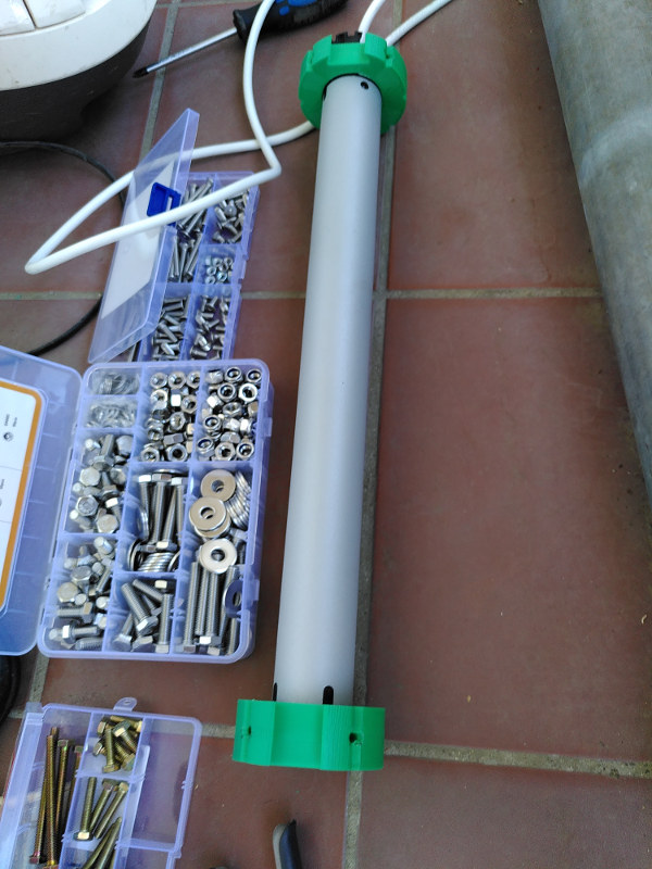
some holding piece on one end with a ball bearing for the whole thing to turn smoothly, and again, note how the plastic is just a proxy between metallic parts ; you can see the ball bearing encased in the plastic:
on the engine’s side, fillers that would match the engine’s octagonal and somewhat weird shapes on the inside, and the cylinder on the outside,
drilling holes in the shaft to host the holding screws:
Fitting the pieces together:
Putting the external support in place:
This last piece has several functions.
first, to hold the whole structure vertically: engine+roller. This is achieved thanks to the 4 horizontal screws, which actually are the ones taking all the weight.
second, to enable rotating the whole structure while blocking on the hexagonal corners, this can be useful if the whole thing becomes stuck, for instance, otherwise you would be in trouble with a non-rotating shutter and no way of unscrewing it due to the lack of space,
third, to have those 3 screws distribute the load of the rotational forces to the 4 horizontal screws. Again, the plastic is just a proxy here, it doesn’t actually hold anything by itself.
Final setup
Finally, everything looks good:
The last step is the electric setup with a switch (notice the little 3D-printed box under it to hide the electric wiring):
Upon testing, everything works as expected. Hurray!
Just a final note to those of you who do have shutters like this: you *have* to lubricate the sliding parts regularly (at least twice a year) with silicone lubricant. It is the best way of giving a long life to your shutters. Any other solution I tried ended up either in disaster or with very unsatisfactory results.
This week-end’s project was focused around building a simple indicator on my desk that alerts me of any problem at home in real time. That way, I don’t need to regularly check things around. Well, this may sound overkill for many people. But over the years, I’ve written a program to monitor many things around me without the need to perform a regular check myself. The only thing I was missing was some real-time indicator that would alert me whenever something urgently needed my attention.
Computers. I am a computer engineer, and as such I do have a few electronic equipment around. I also monitor the temperature, humidity in and out of the apartment and also water leaks with sensors, as I have some sensitive musical instruments in my home. In the past 2 months, the temperatures here have gone up to 37 degrees Celsius several times. These measurements have helped us, without air conditioning (any form of heat pump makes things worse for the environment on the long term), to mitigate the heat. We could close everything when outside was hotter than inside, and open in the evening when the temperatures outside were coming close to the temperature inside.
Here are the temperatures my system measured for the last 5 days:
Where I came from
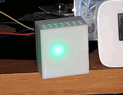
I already had a raspberry pi set up with a tiny monitor showing all the indicators and a big green light (or orange or red) showing the overall status. Something like this:
But this screen consumes 2.5 Watts when it is on, and only 0.15 Watt when it is off. This is a substantial difference, not even mentioning how much wear it causes the screen to be constantly on, just to show a green light!
The solution
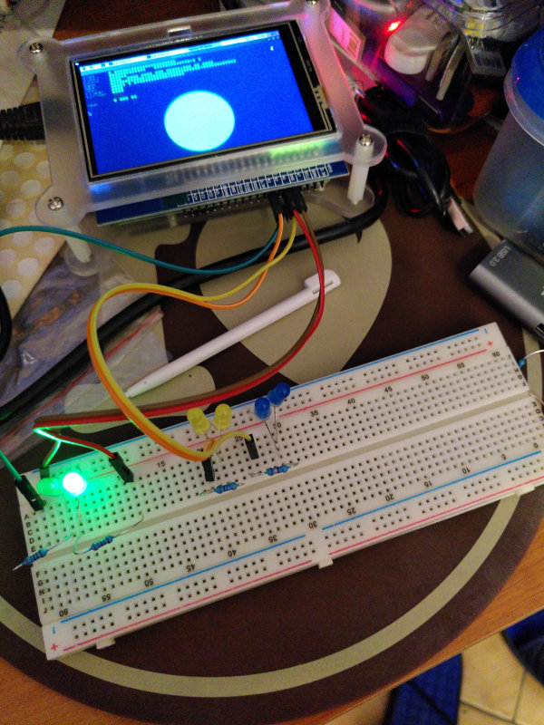
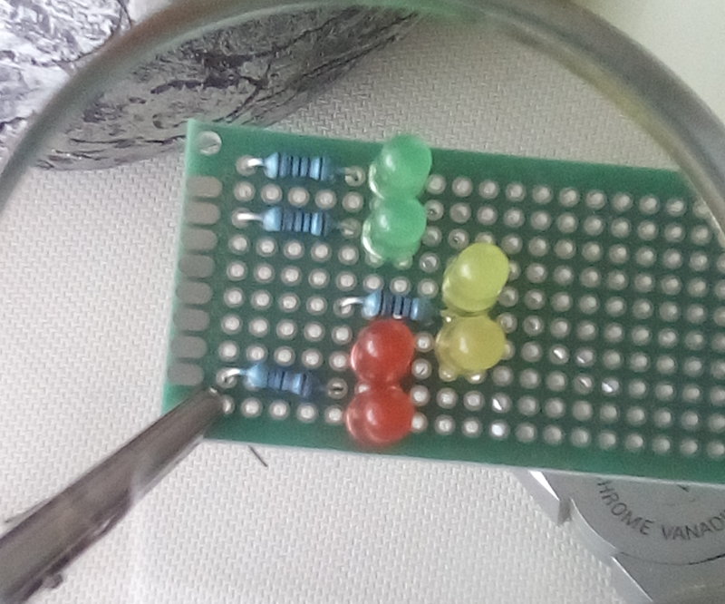
A simple solution: use simple LEDs (which consume virtually nothing) controlled by the raspberry. So I built a first circuit to test the whole thing out:
Of course, that also works with the screen off, that’s the goal after all!
A printed circuit
I had to arrange things together on a smaller plate:
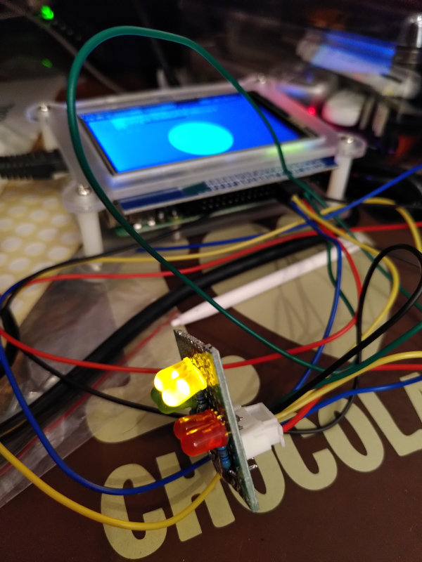
… and solder the whole thing together (yes I butchered the soldering, sorry):
That was a mess…
Buddha (you can see his legs on top of the picture) had a hard time coping with the mess, but he played his role perfectly and went into a deep meditation:
And of course I then had to use this very useful piece of equipment for the cables:
Trying it out
The first testing worked out as expected.
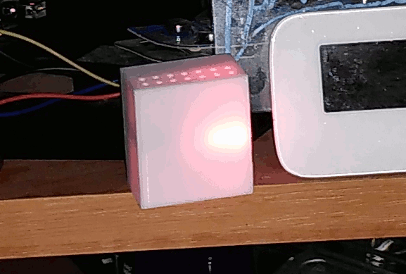
I just needed to print a little box for it with the 3D printer:
Final words…
You might wonder why there are two alternating green lights. Actually, using a single green LED was not an option. If it was constantly on and green, then I wouldn’t be able to know if the program that controls the indicator is still running… or if it has crashed. Of course, I could make one single LED blink… but any blinking inevitably catches the eye and is bothering. On the other hand, two alternating green lights don’t catch the eye because the overall luminosity is constant, while ensuring that the program is alive.
Of course, the error state with a red light and the warning state with an orange light are blinking to make sure that my eye will instantly see it:
You might have noticed that I also have doubled those, this time it is a simple redundancy in case one of the LEDs fail (which is not very likely any time soon given how robust those LEDs are). Besides, I found the luminosity of a single LED a little bit weak, so I preferred having two LEDs with a stronger resistance and thus less strain on each individual LED.
And now I have an indicator on my desk telling me at all times that everything is ok. Or not.
Here is another short blog post showing the use of 3D printing against planned obsolescence… or simply the inevitable wear of objects, even when they are well designed. There was a part 1 and part 2 before this one.
The problem
In this particular case, I had a perfectly functional object… except for one little part:
As you can notice, the plastic piece that is supposed to hold the paper roll has broken. And it is not a simple fix with some glue:
Designing a solution
Fortunately, thanks to 3D printing, we can now print the same piece at home. Some 3D scanners out there can quickly scan the piece to print an exact copy. However, a broken part generally signals a weakness in the design. This is actually confirmed by the other, symmetrical, piece which started cracking in the exact some area. So printing the same piece would lead to the same problem later. Thus I redesigned it, adding some reinforcements in the area where it broke.. This way, I will reprint the piece with a stronger structure in the places where there is most tension:
Implementing the solution
And now we just need to print it:
The result looks good and quite similar to the original except it’s stronger in the weaker parts:
The main difficulty of this piece was the part that plugs into a rail on the main dispenser. The rail had to be precise enough to allow moving without being too loose.
And it is finally fixed!
Now I am waiting for the left arm to break – it will be a piece of cake to replace it.
Conclusion
Think of all the metal and plastic that could be saved if we repaired our objects instead of systematically buying new ones!
Have you ever had a problem with you vacuum cleaner where the electric cord just won’t stay out and will annoyingly get back inside the machine slowly? Like this:
Well, that happened to me. You can of course open it and try to figure out which piece is having a problem. But there’s a good chance that it won’t fix it for good and the problem will come back – that’s the whole point of programmed obsolescence.
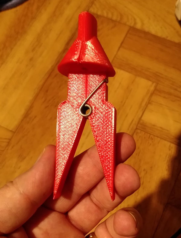
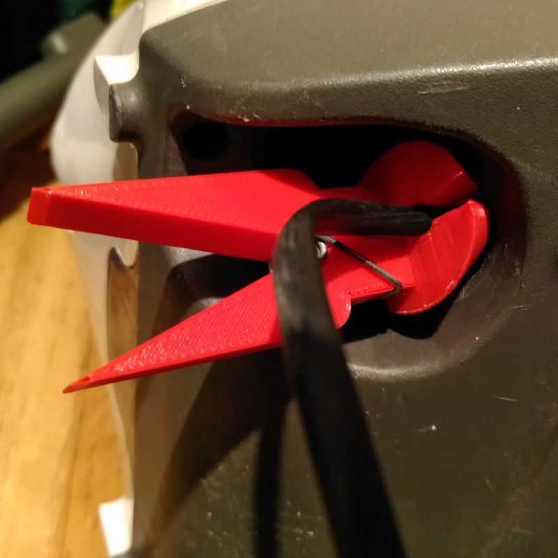
So I designed a very simple clip to hold the wire in place, using the spring of a normal clothes peg – which by the way turned out to be very impractical as a temporary fix.
Here is the result:
Plain and simple, and downloadable on my thingiverse page, as usual.
So, here we go, Planned Obsolescence 0 – 3D Printing 2. 🙂
Recently, I got a package with broken stuff in it. It was actually some shelves with doors, and the broken part was that plastic part that contains magnets which hold the doors closed. Here is a picture of what I received:What generally happens in this kind of circumstance is that people will complain and return the package, then get another brand new article. That’s a lot of wasted transport and energy for such a little missing piece.
So I decided to 3D print the part. In the process, I decided to make it more ergonomic. Those white plastic parts are generally a little sharp and can even scratch your hand if you’re not careful. So I designed a round one. I also had some round magnets around and I decided to use those rather than the stock ones which are rectangular.
As the shelves were made of wood, I also printed that part with wood PLA. Here is the resulting piece with the original near it:
Then I glued the magnets in place:
And here is the final result:
Isn’t that much cooler than the original? I love 3D printing!
It is not the first time that I fix something with 3D printing. But this one was an interesting one!
The problem
A few years ago, I bought two stands for my microphones. Okay, they were inexpensive, and maybe it was a bad long-term choice. Maybe I should have opted for more expensive ones. But I have noticed that higher prices don’t always mean better quality. These days, they often mean higher reseller margins.
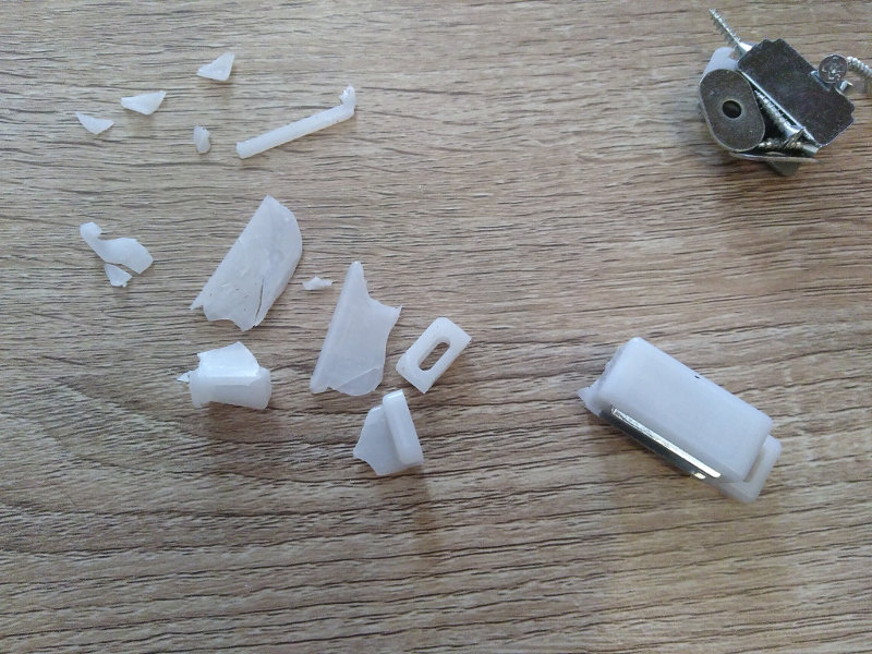
Anyway, both stands were poorly designed. Even though they did last several years, they finally broke recently, roughly at the same time. Unsurprisingly, the faulty piece is a part made of plastic. It sustains high pressure on a very small surface. And after a while, it just gave in. I believe that, without me noticing, cracks developed over time, until they became big enough to break the piece completely:
As you can see, it is pretty bad. Of course, I couldn’t find spare pieces, especially as these are already “old” (anything beyond a year is “old” nowadays). And without this piece, the stands are totally unusable.
Reflexes…
The first reflex was: it’s cheap stuff, I can buy new stands! Why bother for 20 euros?
But apart from this broken piece, those stands are in perfect condition and they could serve their purpose for many more years. Why pay? Why extract more metals from the Earth, build more plastic pieces mostly from petroleum, more rubber from trees or worse from petroleom again, use energy to forge, heat, assemble, then use again more energy to ship those new stands to me or go and fetch them from a local store – where they would have been shipped from somewhere anyway? And dispose from transport boxes that kill trees? As well of course as disposing from the broken stands. And as a result buy new stands in a few years when those new ones will break?
I didn’t actually want any of that, especially as I have the “Planned Obsolescence Killer” at home : a 3D printer!
Compared to all the waste of buying brand new stands, printing a piece is quite environment-friendly: it does use some electricity (not much), and I mainly print using PLA, which is basically made of… corn. This material does have its pros and cons, but it is certainly better than petroleum-based plastic.
Designing a solution
I spent some time designing a solution. This piece allows the axis to be rotated to the desired angle, and it is a functionality that is really needed for this kind of object! So even though there were many alternative ways of fixing that stand, I wanted to stick with the original design as much as possible.
On the other hand, printing this kind of piece with PLA was going to get me in the exact same trouble in a few years: the plastic would certainly not resist the pressure. I could also print with nylon, but I try to avoid it as much as possible due to environmental concerns. Besides, given the pressure on that piece, I wouldn’t be so sure that even nylon would resist for a long time.
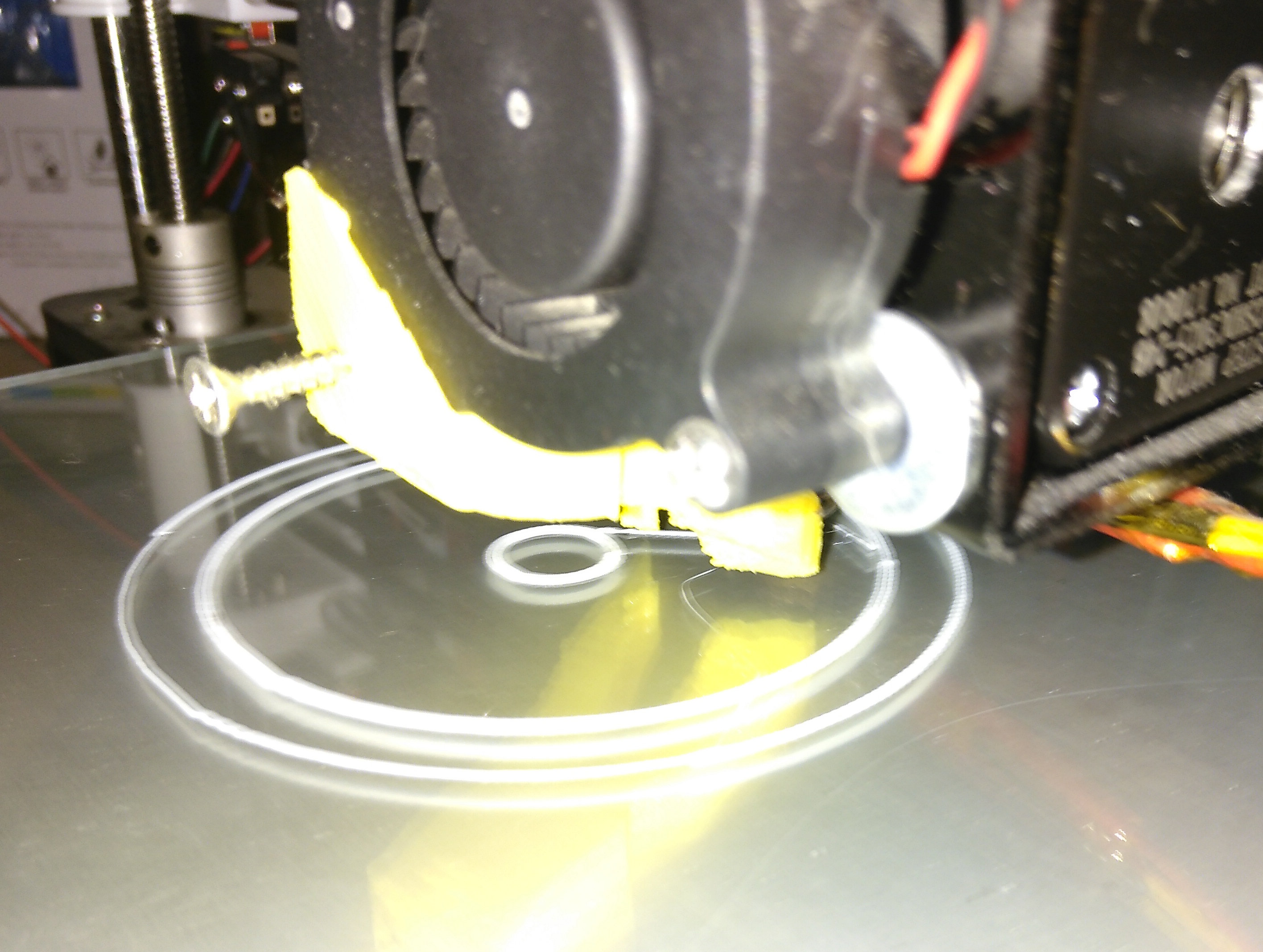
I first thought of adding washers to maximize the surface in contact, but I finally came up with using nuts with a ring base.
3D modelling and printing
Here is one part of the final model:
I heated the printer and printed the pieces:
Results
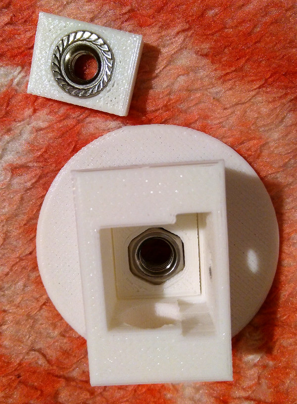
That piece has two other pieces which hold the nuts in place and stop them from turning, even if the pressure actually isn’t a rotating one but a pulling one.
Mounting the nuts in place and putting one of the pieces in its socket:
The socket for the second piece is clearly visible. The final mounted piece:
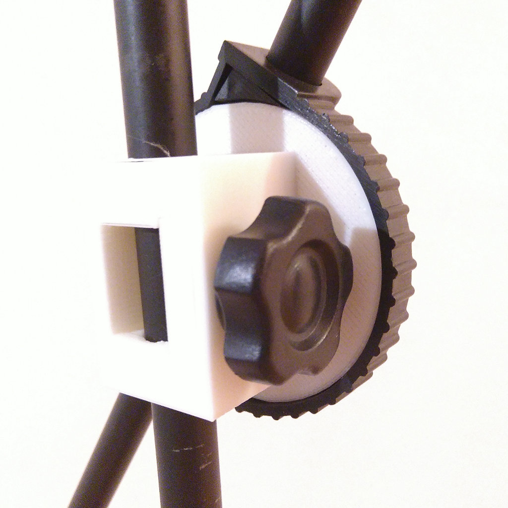
And now it was just a matter of putting it instead of the old piece:
Et voilà ! Both stands are fixed with just a few grams of PLA. I think they will last some more years. In fact, I believe this kind of thing should last at least for a lifetime. But then, how would we sustain “economic growth” to pay for growing banking interests?


 Planned Obsolescence, 0 – 3D Printer, 1
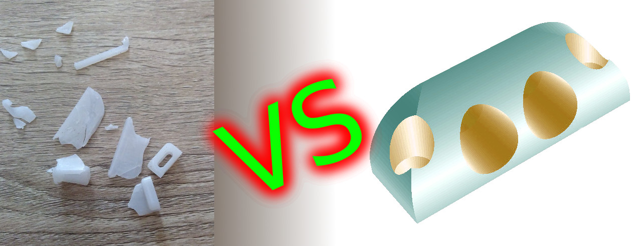 Broken Stuff 0 – 3D Printing 1
 Planned Obsolescence, 0 – 3D Printer, 2
 Planned Obsolescence 0 – 3D Printer 3